manual lathe

Manual lathes, foundational machine tools, shape materials through controlled cutting. These machines, utilizing various parts like beds and headstocks, have a rich historical development.
Understanding their advantages and disadvantages is crucial for effective application in diverse lathe operations, from basic turning to complex profiling.
1.1 What is a Manual Lathe?

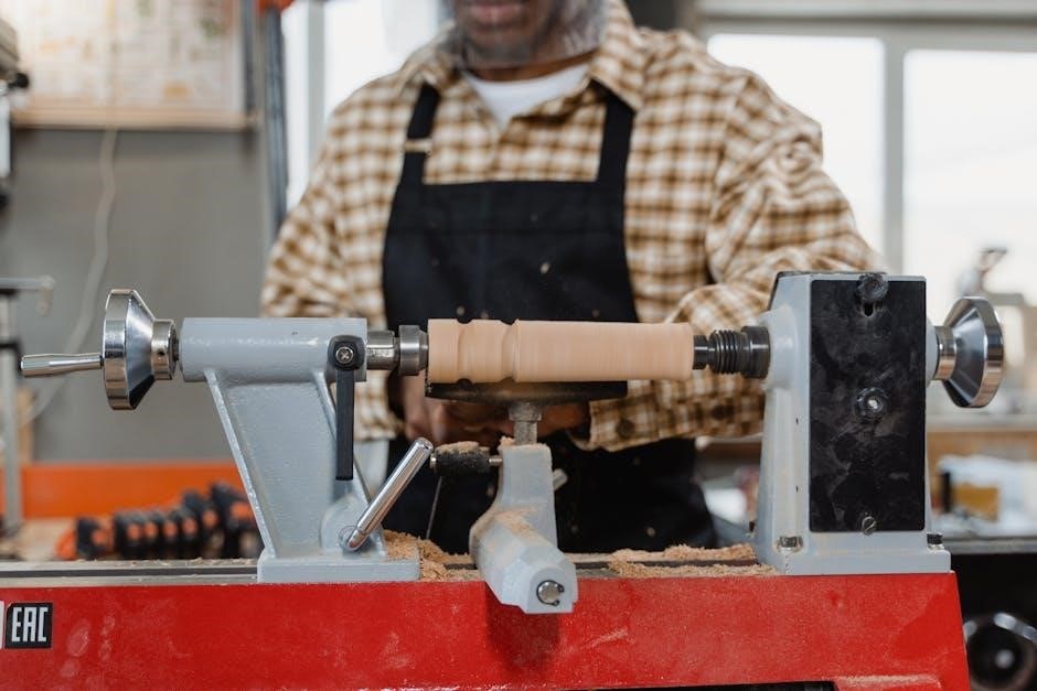
A manual lathe is a machine tool that rotates a workpiece against a single-point cutting tool to perform various operations like turning, facing, and drilling. Unlike CNC lathes, it relies on the operator’s skill and manual control for all movements. The core principle involves securing the material and spinning it at a controlled speed while the tool is fed into the work.
Historically, these lathes were powered by foot or water wheels, evolving into electric motor-driven machines. Key parts include the bed providing stability, the headstock housing the drive mechanism, and the tailstock supporting the workpiece. Operators manipulate handwheels and levers to position the cutting tool, achieving desired shapes and dimensions. It’s a versatile tool for creating cylindrical parts, often used for prototyping and small-batch production.
1.2 Historical Development of Lathes
The origins of the lathe trace back to ancient Egypt around 1300 BC, initially used for woodworking with a bow drill. Roman artisans further refined the design, employing a drive cord for greater efficiency. During the Middle Ages, the lathe evolved with the introduction of the treadle, allowing hands-free operation.
The 18th and 19th centuries witnessed significant advancements with the advent of the screw-cutting lathe, enabling the precise creation of threaded parts. The Industrial Revolution spurred further innovation, leading to more robust and accurate machines. Early lathes were primarily powered by water or steam, transitioning to electric motors in the 20th century. These manual machines remained central to manufacturing until the rise of CNC technology, yet continue to be valuable for specific applications and skill development.
1.3 Advantages and Disadvantages of Manual Lathes
Manual lathes offer distinct advantages, notably their lower initial cost compared to CNC counterparts. They excel in small-batch production and prototyping, providing flexibility for unique parts. Skilled operators can achieve high precision and intricate designs, fostering a deep understanding of machining principles. Furthermore, they require less electrical power and are simpler to maintain.
However, manual lathes also present limitations. Production speed is inherently slower, relying heavily on operator skill and fatigue. Achieving consistent accuracy across larger production runs can be challenging. They demand significant operator training and experience, and are less suitable for complex geometries or automated processes. The reliance on manual control also introduces a higher risk of human error during lathe operations.
Key Components of a Manual Lathe
Manual lathes comprise essential parts: the bed, headstock, tailstock, carriage, and feed mechanism. These components work in harmony to facilitate precise lathe operations.
2.1 Bed
The bed is the foundational component of any manual lathe, serving as the robust base upon which all other parts are mounted. Typically constructed from cast iron due to its excellent vibration damping characteristics and rigidity, the bed provides crucial stability during machining operations.
It features precisely machined ways – horizontal surfaces – that guide the movement of the carriage and tailstock. These ways are often hardened and ground to ensure smooth, accurate travel. The bed’s length directly influences the maximum workpiece length that can be accommodated.

Furthermore, the bed often incorporates features like V-ways and flat ways to provide secure and precise support for various workpiece shapes. The structural integrity of the bed is paramount for maintaining the overall accuracy and performance of the lathe.
2.2 Headstock
The headstock of a manual lathe is a critical assembly housing the main spindle and drive mechanism. It’s responsible for rotating the workpiece at varying speeds, essential for different lathe operations. Within the headstock, a motor transmits power through belts and gears, or sometimes directly, to the spindle.
A key feature is the speed change mechanism, allowing operators to select optimal cutting speeds based on the material and tool being used. This is often achieved through a gear train or cone pulley system. The spindle itself is supported by bearings, ensuring smooth and accurate rotation.
The headstock’s rigidity and precision are vital for maintaining workpiece accuracy. It also often incorporates a chuck mounting flange, allowing for secure attachment of workholding devices.
2.3 Tailstock
The tailstock is a crucial component of a manual lathe, positioned opposite the headstock. Its primary function is to provide support to the workpiece, especially during longer turning operations. This support prevents deflection and ensures accuracy.
The tailstock features a quill, a cylindrical shaft that extends and retracts, allowing it to be adjusted to match the workpiece length. This quill typically houses a center, which provides the actual support. The quill’s movement is controlled by a handwheel or lever.
Beyond support, the tailstock can also hold tools for specific lathe operations like drilling or reaming. Its base can be moved along the lathe bed and clamped into position, offering versatility. Proper alignment of the tailstock is essential for achieving precise results.
2.4 Carriage and Tool Post
The carriage on a manual lathe is the assembly that moves along the lathe bed, supporting and controlling the cutting tool. It’s a fundamental element for performing various lathe operations. Mounted on the carriage is the tool post, which securely holds the cutting tool itself.
The carriage typically has both manual and automatic feed mechanisms, allowing for precise control of the cutting depth and speed; Different types of tool posts exist – most commonly, a four-way tool post allows for quick tool changes and versatile positioning.
The carriage’s movement, combined with the tool post’s adjustability, enables operations like turning, facing, and boring. Ensuring the carriage moves smoothly and accurately is vital for achieving the desired workpiece dimensions and surface finish.
2.5 Feed Mechanism
The feed mechanism of a manual lathe controls the rate at which the cutting tool advances into the workpiece. This is crucial for achieving the desired cut depth and surface finish during lathe operations. Typically, manual lathes offer both longitudinal and crossfeed options.
Longitudinal feed moves the tool along the length of the workpiece, used for turning and facing. Crossfeed moves the tool perpendicular to the workpiece axis, essential for operations like boring and creating tapers. The feed rate can be adjusted manually via handwheels or selected using a gear train.
Precise feed control is paramount; too fast a feed can damage the tool or workpiece, while too slow a feed can lead to excessive heat buildup. Skilled operators carefully adjust the feed based on the material and cutting tool used.

Basic Lathe Operations
Manual lathe proficiency involves mastering core techniques like turning, facing, drilling, and boring. These operations, utilizing various cutting tools, shape materials with precision and control.
3.1 Turning (Straight, Taper)
Turning is a fundamental manual lathe operation, reducing a workpiece’s diameter. Straight turning creates cylindrical surfaces with a consistent diameter along the length, achieved by moving the cutting tool parallel to the lathe’s axis.
Taper turning, however, produces a conical surface. This can be accomplished using the compound rest, set at an angle, or by utilizing the tailstock offset method. The compound rest allows for precise, gradual tapers, while the tailstock offset is suited for longer, steeper tapers.
Proper tool selection and feed rates are critical for both types of turning. Maintaining consistent pressure and speed ensures a smooth finish and accurate dimensions. Understanding the material being turned is also vital, as different materials require varying cutting parameters. Careful monitoring and adjustment are key to successful turning.
3.2 Facing
Facing on a manual lathe is the process of creating a flat surface perpendicular to the workpiece’s axis. This operation is essential for establishing a reference surface and ensuring accurate dimensions. The cutting tool moves radially across the workpiece’s end, removing material to achieve the desired flatness.
Typically, facing begins with a roughing cut to quickly remove larger amounts of material, followed by a finishing cut for a smoother surface. Maintaining a consistent feed rate and depth of cut is crucial for a uniform finish. The operator must carefully control the tool’s movement to avoid chatter or excessive tool wear.
Proper workholding and tool setup are paramount for accurate facing. Ensuring the workpiece is securely mounted and the tool is sharp and properly aligned will yield optimal results. Facing is often a preliminary step before other lathe operations.
3.3 Drilling
Drilling on a manual lathe allows for creating precise holes in rotating workpieces. Unlike a drill press, the lathe’s rotational motion assists the cutting process, enhancing accuracy and finish. A specialized drill chuck, mounted in the tailstock, securely holds the drill bit.
The process involves feeding the drill bit into the workpiece while the workpiece rotates at an appropriate speed. Careful control of the feed rate is vital to prevent breakage or a poor-quality hole. Pecking cuts – incrementally advancing the drill – are often used for deeper holes to clear chips effectively.
Coolant is frequently applied during drilling to lubricate the bit and dissipate heat. Proper drill bit selection, based on material and hole size, is essential. Drilling on a lathe is a versatile technique for creating features needed for subsequent lathe operations.
3.4 Boring
Boring on a manual lathe expands existing holes to a precise diameter, offering greater accuracy than initial drilling. Unlike drilling, which creates a new hole, boring refines an existing one. A boring bar, securely mounted in the tool post, holds the cutting tool.
The workpiece rotates while the boring bar is fed radially into the hole. This process gradually removes material, increasing the hole’s diameter. Boring is crucial for achieving tight tolerances and smooth surface finishes. Internal threading can also be performed using specialized boring tools.
Maintaining rigidity and using appropriate cutting speeds are vital for successful boring. Coolant application is essential for heat dissipation and chip removal. Boring complements drilling and other lathe operations, enabling the creation of complex internal features.
Tools Used in Manual Lathe Operations
Manual lathe work relies on cutting tools – high-speed steel or carbide – held by robust tool holders. Precise measuring instruments, like calipers and micrometers, ensure accuracy.
4.1 Cutting Tools (High-Speed Steel, Carbide)
Cutting tools are paramount in manual lathe operations, dictating the quality and efficiency of material removal. High-Speed Steel (HSS) tools are widely used due to their affordability and ability to be sharpened repeatedly, making them suitable for general-purpose machining and lower production runs.
However, carbide tools offer significantly higher hardness and wear resistance, allowing for faster cutting speeds and feeds, especially when working with harder materials. While initially more expensive, carbide tools maintain a sharp edge for longer periods, reducing downtime for sharpening and improving surface finish.
The selection between HSS and carbide depends on factors like material being machined, production volume, and desired surface finish. Different geometries and coatings further optimize tool performance for specific applications, ensuring optimal cutting action and tool life. Proper tool selection is crucial for achieving precise and efficient machining results.
4.2 Tool Holders
Tool holders are essential components in manual lathe operations, securely clamping and precisely positioning cutting tools within the tool post. These holders come in various designs, including quick-change tool posts which significantly reduce setup time by allowing rapid tool changes without re-alignment.
Common types include shank-type holders, which directly fit into the tool post, and specialized holders for specific tool geometries like boring bars or threading tools. Rigidity is paramount; a secure grip minimizes vibration and chatter, ensuring accurate cuts and extending tool life.
Proper tool holder selection and alignment are critical for achieving desired tolerances and surface finishes. Maintaining cleanliness and ensuring a tight fit between the tool, holder, and tool post are vital for safe and efficient machining. Regular inspection for wear or damage is also recommended.
4.3 Measuring Instruments (Calipers, Micrometers)

Precise measurement is fundamental to successful manual lathe work. Calipers and micrometers are indispensable measuring instruments used to verify workpiece dimensions and ensure accuracy throughout the machining process. Calipers, both dial and digital, measure outside, inside, and depth dimensions with reasonable precision.
Micrometers, offering higher accuracy, are ideal for measuring diameters and thicknesses. Proper technique is crucial; avoid excessive force when tightening the spindle and always read the scale correctly. Regular calibration of these instruments is essential to maintain their accuracy.

Other useful tools include depth gauges and bore gauges for specific measurements. Utilizing these instruments allows operators to maintain tight tolerances and produce parts meeting specified requirements, contributing to overall quality control.

Safety Precautions for Manual Lathe Operation

Manual lathe operation demands strict adherence to safety protocols. Personal Protective Equipment (PPE), like eye protection, is vital. Following safe procedures and knowing emergency stop functions are crucial.
5.1 Personal Protective Equipment (PPE)
Personal Protective Equipment (PPE) is paramount when operating a manual lathe. Eye protection, specifically safety glasses or a face shield, is non-negotiable, safeguarding against flying chips and coolant spray. These projectiles can cause severe injury.
Appropriate clothing is also essential. Avoid loose garments, jewelry, and anything that could become entangled in the rotating machinery. Long sleeves offer some protection, but should be secured. Sturdy, closed-toe shoes are mandatory, protecting feet from dropped tools or materials.
Hearing protection, such as earplugs or earmuffs, may be necessary in noisy environments. Finally, consider a shop apron to protect clothing from oil, coolant, and metal shavings. Consistent use of proper PPE significantly reduces the risk of injury during lathe operations.
5.2 Safe Operating Procedures
Safe operating procedures are critical for preventing accidents with a manual lathe. Always ensure the workpiece is securely clamped in the chuck or between centers before starting the machine. Double-check all adjustments and guards are in place.
Never leave the lathe running unattended. Maintain a safe distance while the machine is in operation, and avoid reaching over or around moving parts. Use appropriate cutting speeds and feeds for the material being machined.
Properly lubricate the lathe according to the manufacturer’s recommendations. Keep the work area clean and free of debris. Before making any adjustments, always stop the lathe and disconnect the power. Regular inspection and maintenance contribute to safe operation.
5.3 Emergency Stop Procedures
In an emergency, knowing the manual lathe’s emergency stop procedures is paramount. Immediately press the large, red emergency stop button located prominently on the machine. This will cut power to the spindle and other moving components.
If the emergency stop fails, disconnect the main power supply to the lathe. Assess the situation carefully before attempting to restart the machine. Report any incidents or malfunctions to a supervisor or qualified technician.
Ensure everyone in the vicinity is aware of the emergency stop location and procedures. Regular drills can reinforce these procedures. Never bypass or disable safety features. Prioritize personal safety and prevent further damage by following these critical steps.